 DDR2 Memory Overview
Dell™ OptiPlex™ GX620
User's Guide
Addressing Memory With 4-GB Configurations
Replacing/Adding Additional Memory
For information on the type of memory supported by your computer, see the "Memory" section of the specifications for your computer:

|
NOTICE: Before you install new memory modules, download the most recent BIOS for your computer from the Dell Support website at support.dell.com. |
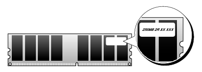
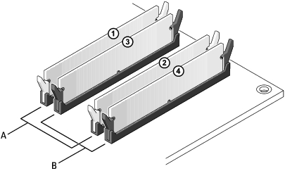
Dual-channel DDR2 memory modules should be installed in pairs of matched memory size. If the DDR2 memory modules are not installed with the same amount of memory in each channel, the computer will continue to operate, but with a slight reduction in performance. See the label in the upper-right corner of the module to determine the module's capacity.

|
NOTE: Always install DDR2 memory modules in the order indicated on the system board. |
The recommended memory configurations are:
or
or
|
|
NOTICE: Do not install ECC memory modules. Doing so may cause the system not to boot or affect performance. |
Be sure to install a single memory module in DIMM1, the connector closest to the processor, before you install modules in the other connectors.
|
|
NOTE: The ultra small form factor computer has only two slots which are considered an interleaved pair. The mini tower, desktop, and small form factor computers have four slots. |
|
A |
matched pair of memory modules in connectors DIMM1 and DIMM2 (white securing clips) |
|
B |
matched pair of memory modules in connectors DIMM3 and DIMM4 (black securing clips). |
This computer supports a maximum of 4 GB of memory when you use four 1-GB DIMMs or two 2-GB DIMMs. Current operating systems, such as Microsoft® Windows® XP, can only use a maximum of 4 GB of address space; however, the amount of memory available to the operating system is less than 4 GB. Certain components within the computer require address space in the 4-GB range. Any address space reserved for these components cannot be used by computer memory.
The following components require memory address space:
At start-up, the BIOS identifies the components that require address space. The BIOS dynamically calculates the amount of reserved address space required. The BIOS then subtracts the reserved address space from 4 GB to determine the amount of usable space.

|
CAUTION: Before you begin any of the procedures in this section, follow the safety instructions in the Product Information Guide. |
|
|
NOTICE: If you remove your original memory modules from the computer during a memory upgrade, keep them separate from any new modules that you may have, even if you purchased the new modules from Dell. If possible, do not pair an original memory module with a new memory module. Otherwise, your computer may not start properly. You should install your original memory modules in pairs either in connectors DIMM1 and DIMM2 or connectors DIMM3 and DIMM4. |
|
|
NOTICE: Removing memory modules from DIMM2 and DIMM4 on the desktop computer requires you to remove the optical drive (see "Drives"). Failure to do so may cause damage to the memory module and the DIMM socket. |
|
|
NOTE: Memory purchased from Dell is covered under your computer warranty. |
|
1 |
memory module |
|
2 |
securing clip (2) |
|
|
CAUTION: Before you begin any of the procedures in this section, follow the safety instructions in the Product Information Guide. |
|
|
NOTICE: To prevent static damage to components inside your computer, discharge static electricity from your body before you touch any of your computer's electronic components. You can do so by touching an unpainted metal surface on the computer chassis. |
|
|
NOTE: Memory purchased from Dell is covered under your computer warranty. |
|
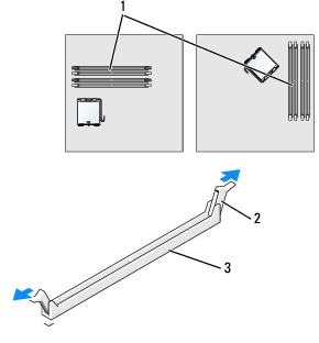
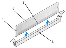
1 |
memory connector closest to processor |
|
2 |
securing clips (2) |
|
3 |
connector |
|
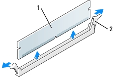
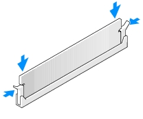
1 |
cutouts (2) |
|
2 |
memory module |
|
3 |
notch |
|
4 |
crossbar |
|
|
NOTICE: To avoid damage to the memory module, press the module straight down into the connector while you apply equal force to each end of the module. |
If you insert the module correctly, the securing clips snap into the cutouts at each end of the module.
The amount of system memory has changed.
Strike the F1 key to continue, F2 to run the setup utility
The computer should have changed the value of System Memory to reflect the newly installed memory. Verify the new total. If it is correct, skip to step 9.