Back to Contents Page
Dell™ OptiPlex™ GX620
User's Guide
 Power Supply
Power Supply
Replacing the Power Supply

|
CAUTION: Before you begin any of the procedures in this section, follow the safety instructions located in the Product Information Guide. |

|
NOTICE: To prevent static damage to components inside your computer, discharge static electricity from your body before you touch any of your computer's electronic components. You can do so by touching an unpainted metal surface on the computer chassis. |
- Follow the procedures in "Before You Begin."
- Disconnect the DC power cables from the system board and the drives.
Note the routing of the DC power cables underneath the tabs in the computer chassis as you remove them from the system board and drives. You must route these cables properly when you replace them to prevent their being pinched or crimped.
- Remove the two screws that attach the power supply to the back of the computer chassis.
- Remove the CD/DVD drive and carefully set it aside.
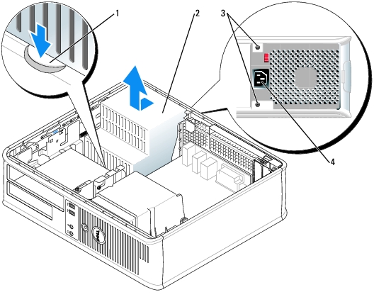
- Press the release button located on the floor of the computer chassis.
|
1
|
release button
|
|
2
|
power supply
|
|
3
|
screws (2)
|
|
4
|
AC power connector
|
- Slide the power supply toward the front of the computer by approximately 1 inch.
- Lift the power supply up and out of the computer.
- Slide the replacement power supply into place.
- Replace the screws that secure the power supply to the back of the computer chassis.
- Reconnect the DC power cables.
- Replace the CD/DVD drive.
- Connect the AC power cable to the connector.
- Replace the computer cover.
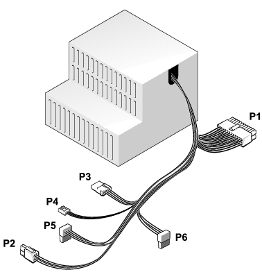
DC Power Connectors
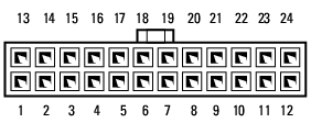
DC Power Connector P1
|
Pin Number
|
Signal name
|
18-AWG Wire
|
|---|
1
| +3.3 VDC
| Orange
|
2
| +3.3 VDC
| Orange
|
3
| GND
| Black
|
4
| VCC (+5 V)
| Red
|
5
| GND
| Black
|
6
| VCC (+5 V)
| Red
|
7
| GND
| Black
|
8
| PS_PWRGOOD
| Gray
|
9
| P5AUX
| Purple
|
10
| V_12P0_DIG
| Yellow
|
11
| V_12P0_DIG
| Yellow
|
12
| +3.3 V
| Orange
|
13
| +3.3 V
| Orange
|
14
| -12 V*
| Blue
|
15
| GND
| Black
|
16
| PWR_PS_ON
| Green
|
17
| GND
| Black
|
18
| GND
| Black
|
19
| GND
| Black
|
20
| NC
| N/C
|
21
| VCC (+5V)
| Red
|
22
| VCC (+5V)
| Red
|
23
| VCC (+5V)
| Red
|
24
| GND
| Black
|
*Use 22-AWG wire instead of 18-AWG wire.
|
DC Power Connector P2
|
Pin Number
|
Signal Name
|
18-AWG Wire
|
|---|
1
| COM
| Black
|
2
| COM
| Black
|
3
| +12 VDC
| Yellow
|
4
| +12 VDC
| Yellow
|
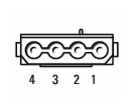
DC Power Connector P3
|
Pin Number
|
Signal name
|
18-AWG Wire
|
|---|
1
| +12VDC
| Yellow
|
2
| COM
| Black
|
3
| COM
| Black
|
4
| +5 VDC
| Red
|
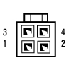
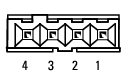
DC Power Connector P4
|
Pin Number
|
Signal Name
|
22-AWG Wire
|
|---|
1
| +5 VCD
| Red
|
2
| COM
| Black
|
3
| COM
| Black
|
4
| +12 VDC
| Yellow
|
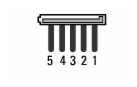
DC Power Connector P5 and P6
|
Pin Number
|
Signal name
|
18-AWG Wire
|
|---|
1
| +3.3 VDC
| Orange
|
2
| COM
| Black
|
3
| +5 VDC
| Red
|
4
| COM
| Black
|
5
| +12 VDC
| Yellow
|
Back to Contents Page