Power Supply
Dell™ OptiPlex™ GX620
User's Guide

|
CAUTION: Before you begin any of the procedures in this section, follow the safety instructions located in the Product Information Guide. |

|
NOTICE: To prevent static damage to components inside your computer, discharge static electricity from your body before you touch any of your computer's electronic components. You can do so by touching an unpainted metal surface on the computer chassis. |
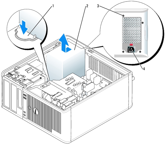
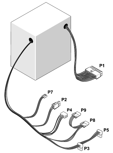
Note the routing of the DC power cables underneath the tabs in the computer chassis as you remove them from the system board and drives. You must route these cables properly when you replace them to prevent them from being pinched or crimped.
|
1 |
release button |
|
2 |
power supply |
|
3 |
screws (4) |
|
4 |
AC power connector |
|
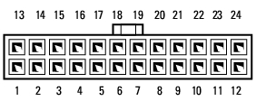
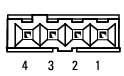
Pin Number |
Signal Name |
18-AWG Wire |
|---|---|---|
1 | COM | Black |
2 | COM | Black |
3 | +12 VDC | Yellow |
4 | +12 VDC | Yellow |
|
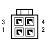
Pin Number |
Signal name |
18-AWG Wire |
|---|---|---|
1 | +3.3 VDC | Orange |
2 | COM | Black |
3 | +5 VDC | Red |
4 | COM | Black |
5 | +12 VDC | Yellow |
|
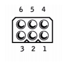
Pin Number |
Signal name |
18-AWG Wire |
|---|---|---|
1 |
| N/C |
2 | COM | Black |
3 | COM | Black |
4 | + 3.3 VDC | Orange |
5 | +5 VDC | Red |
6 | +12 VDC | Yellow |
|
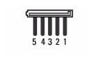
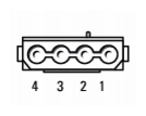
Pin Number |
Signal Name |
22-AWG Wire |
|---|---|---|
1 | +5 VCD | Red |
2 | COM | Black |
3 | COM | Black |
4 | +12 VDC | Yellow |
Pin Number Signal name 18-AWG Wire 1 +12 VDC Yellow 2 COM Black 3 COM Black 4 +5 VDC Red